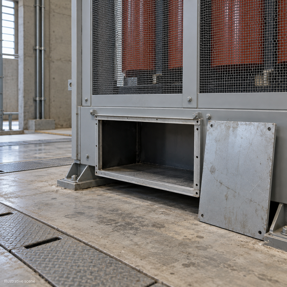
Dry-type transformer LV cable connections need a complete interface review before quotation acceptance. Coordinate the cable route, conductor and lug, terminal geometry, support arrangement, and joint-specific assembly instructions. Request a dimensioned interface drawing tied to the proposed cable schedule. Matching voltage and kVA ratings alone do not establish cable fit or acceptance of the intended termination arrangement.

This guide is for EPC engineers and procurement teams reviewing dry-type transformers for IEC-specified industrial projects with cable-connected LV circuits up to 1 kV. Destination rules and the approved project design still govern. It is a procurement checklist, not an installation procedure; electrical work belongs to qualified personnel under the applicable isolation and safety procedures.
1. Freeze the cable inputs before reviewing terminal space
Use the actual proposed cable data rather than a conductor cross-section alone. Ask the cable designer to identify conductor material, conductor construction, insulation, outside diameter, number of cables per phase, neutral arrangement, entry direction, and the cable manufacturer’s bending requirements.
A useful drawing review starts with a cable schedule that has a revision number. If the cables have not been selected, mark the interface provisional and record the assumptions behind the quotation. For replacement projects, include a surveyed entry position and route; photographs can supplement dimensions but cannot replace them.
- Show the entry-to-terminal route in plan and elevation.
- Identify the relevant cable bending requirement and its source.
- Include the lug body, cable gland, adjacent phases, enclosure panels, and access needed for the specified assembly tools.
- Record which party must approve any later cable-size or cable-count change.
2. Check the cable lug and transformer terminal together
A cable lug must suit both the conductor and the terminal interface. Request the proposed lug reference and drawing, then compare its palm dimensions, hole pattern, orientation, and conductor accommodation with the transformer terminal drawing. Do not treat a matching bolt diameter as a complete compatibility check.
The review should identify the conductor material and size range accepted by the connector, the terminal material and finish, the specified hardware, and any approved treatment or transition needed between dissimilar materials. If multiple cables or lugs are proposed at one terminal, ask for that exact arrangement to be shown and accepted. Spare holes alone do not establish an approved cable count.
IEC 61238-1-1:2018 addresses type tests for compression and mechanical power-cable connectors within its defined scope, including rated voltages up to 1 kV. A connector test reference is useful evidence, but it does not by itself approve a complete transformer termination arrangement. Request the report’s connector identity, conductor coverage, and applicable test classes.
3. Make cable support a separate approval item
The interface drawing should show how the cables are supported and which party supplies that support. Ask the responsible designer to confirm the loads permitted at the transformer terminals and the support arrangement needed for the proposed route, cable formation, and fault duty.
IEC 61914:2021 covers cable cleats and intermediate restraints. Resistance to electromechanical forces applies where declared, and some cleats depend on a specified mounting surface. A product described simply as a “cable clamp” therefore needs further identification before it can close the support review.
Record the selected cleat or restraint, its supporting structure, mounting conditions, and the relevant declared performance. Keep the transformer supplier’s terminal-load confirmation and the installation designer’s support approval together, so an unresolved responsibility does not disappear between purchase orders.
4. Ask for a joint schedule, not one torque number
The assembly documents should identify the torque requirement for each applicable joint and the instruction that controls it. Where a mechanical lug is proposed, distinguish conductor-clamping screws from the hardware attaching the lug to the transformer terminal. For compression lugs, request the specified installation system separately from the terminal-bolt instructions.
For bolted copper busbar joints, the Copper Development Association and European Copper Institute design guide explains that torque selection depends on the joint and fastener conditions. Friction, surface finish, lubrication, bolt material, and operating temperature matter. Its example arrangements are not a universal transformer torque table.
Ask for a schedule that names the joint, drawing reference, hardware specification, applicable surface condition, torque value and unit where relevant, and instruction revision. This guide intentionally gives no tightening values. If two documents disagree, obtain a written resolution for the proposed assembly before release.
5. Release dry-type transformer LV cable connections by drawing
Use one interface register to connect the drawings, component references, and approvals. The following is a suggested procurement record, not a prescribed standard form.
| Review item | Evidence to request | Question to close |
|---|---|---|
| Cable route and space | Coordinated cable schedule and dimensioned layout | Does the proposed route fit the selected cables and access requirements? |
| Lug and terminal | Connector reference and terminal detail | Is the complete connection arrangement accepted? |
| Cable support | Support drawing and relevant performance documentation | Who approves the supports and permitted terminal loads? |
| Assembly requirements | Joint-specific instruction and hardware schedule | Is each joint linked to an unambiguous instruction? |
| Final release | Revision-controlled approval and deviation list | Are unresolved assumptions visible before manufacture? |
For a HEAKOR dry-type transformer enquiry, identify the LV cable interface as a drawing-review item. The product page describes outline-drawing requests covering terminals, access, mounting, and cable entry. A particular lug arrangement, support provision, or torque instruction still requires confirmation for the proposed design.
Flag cable inputs that are still provisional
If the cable selection is incomplete, record the assumed conductor material, cable count, outside diameter, entry direction and lug arrangement beside the drawing revision. Name the party and milestone that will confirm each input. Require another interface review when the selected cable or connector differs from those assumptions; a preliminary outline should not silently become an approved connection drawing.
Keep the approved interface and its revisions with the project technical-document record, including any written resolution of drawing or instruction conflicts.
Frequently asked questions
Can a cable substitution leave the approved interface unchanged?
Only after the responsible parties review the substitution. Compare the new cable and connector data with the approved drawing and record whether the change affects fit, supports, or assembly instructions.
Is a connector certificate enough to accept the transformer connection?
No. Check what connector and conductor combination the document covers. Acceptance also needs the proposed terminal arrangement and the project’s installation requirements.
Should the transformer or cable contractor supply the lugs?
Either arrangement needs a clear supply boundary. Name the supplier, the party approving compatibility, and the documents required before procurement so neither package assumes the other includes the work.
What if the supplier’s drawing and installation manual conflict?
Keep the affected item open and request a coordinated written revision or clarification. Record the document that governs the particular assembly rather than choosing a value from a similar transformer.
Does this checklist also approve a busduct connection?
No. A busduct interface needs its own coordinated design and responsibility review. Do not carry a cable-terminal approval over to a different connection system.
Submit your project specification
Send HEAKOR the transformer duty, destination, cable schedule, proposed entry route, lug data if selected, and drawing-approval requirements. Ask the quotation to identify the proposed interface, exclusions, and documents requiring confirmation. Use the transformer RFQ checklist for the wider electrical and commercial inputs, then submit your project specification.